Recorded a quick video of me using and then breaking ZeroTier-Console.
Any suggestions / feedback welcome! Though I’m aware that there are some misspellings in there at the moment lol
In the previous post, I got the Raspberry Pi outputting the values from the temperature sensors via SNMP.
In this post, I’ll be configuring Zabbix to monitor and record these values so that I can see how cold it was last night.
You’ll need to note down the OIDs that were configured on the SNMP agent in the last post so you can use them in this post.
The Raspberry Pi will need to be monitored in some way by Zabbix in order for us to record the temperatures from the SNMP agent that we’ve set up.
You’ll need to add the Raspberry Pi as a host in Zabbix, and give it an IP address under the SNMP interfaces section. I’ve added the SNMP OS Linux template to monitor the rest of the Pi stats, but that’s not required for monitoring temperatures.
So I got a bit sidetracked from my tear down of the Ritmo CE-3590 NAS, and ended up building a temperature sensor with some DS18B20s and a Raspberry Pi.
Today’s post will detail how I configured the Pi to output the temperature values to the SNMP agent that I’m running on the Pi.
Since I used the DS18B20s, they are polled over a single wire with a 4K7 resistor across the VCC and Data wires.
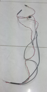
I ended up using a whole bunch of CD Audio cables like this one –

to create the wiring for the sensors. If I had the pins to use between the cables, I could have just joined cables together, but as I didn’t, I cut and soldered multiple cables together. At the end of the wires that will plug into the Pi, I spliced in the 4K7 resistor and heatshrinked it so hopefully it won’t short anything out.

It ended up very messy, but it seems to have worked.
I used the Red wire for 3.3V, the white wire as data, and the black as ground.
Red then gets plugged into the Pi header at Pin 1 which is 3.3V power
White gets plugged into Pin 7 which is GPIO 4
Black gets plugged into Pin 6, which is a ground. This could be any of the other grounds, but this is the closest one.
I’m using Raspbian on my Pi, so any instructions are done with a Raspbian flavour. Most distros should have the same setup though.
The Pi needs to be configured to use the w1-gpio device tree overlay (dtoverlay).
This is done by adding the line dtoverlay=w1-gpio to the end of the config.txt file on the /boot partition.
Once this dtoverlay has been activated, you should be able to see your sensors under /sys/devices/w1_bus_master1/. They should appear as 28-0215**. On my Pi, the sensors appear like so –
/sys/devices/w1_bus_master1/28-0215012018ff

/sys/devices/w1_bus_master1/28-021500ce50ff

/sys/devices/w1_bus_master1/28-021500cfceff
Catting one of the w1_slave nodes under the sensor should output something like this –
57 01 55 00 7f ff 0c 10 05 : crc=05 YES

57 01 55 00 7f ff 0c 10 05 t=21437
The YES confirms the sensor is working, and the temperature is displayed after the t=
In this example, the temperature is 21.437 Degrees Celsius. The output needs to be divided by 1000 to get the temperature to the correct amount of decimal places.
With the sensors plugged in, it’s time to extend the SNMP agent to allow us to poll the temperature sensors over SNMP.
I’ve written a script that will output just the temperature to the SNMP agent, I’ve placed this script in /opt/scripts but you’re free to put it wherever you want. You’ll need to keep the location handy for when we extend the SNMP agent.
I’ve named this script gettemp.sh
#!/bin/bash

#

# Usage: gettemp.sh

# e.g. gettemp.sh 28-0215012018ff

SENSOR=$1

SLAVE="/sys/devices/w1_bus_master1/"$SENSOR"/w1_slave"

OUTPUT=$(/bin/cat $SLAVE | /usr/bin/awk -F 't=' ' { printf $2 } ')

echo $OUTPUT
With this script, you should be able to call the script from a command line, and it should output the temperature for that sensor.
# /opt/scripts/gettemp.sh 28-021500ce50ff

21437
With this script operational, we’ll need to setup the SNMP agent to run this script to provide us the output of this script over SNMP.
To do this, we need to modify /etc/snmp/snmpd.conf. At the end of the file, put in this line –
Make sure you replace the sensor id with your own sensor id. If you want to monitor more than one sensor, add more extend lines, and give them differing names, like temp2, temp3, etc.
extend .1.3.6.1.3.1.1 temp1 /bin/bash /opt/scripts/gettemp.sh 28-021500ce50ff
After you modify the snmpd.conf file, make sure you restart SNMP agent with /etc/init.d/snmpd restart or service snmpd restart.
Once the SNMP agent is back up and running, you should be able to poll the OID we specified above (.1.3.6.1.3.1.1) and get the output of the command. I’ve run the snmpwalk on the Pi itself, polling itself.
# snmpwalk -v 2c -c public 127.0.0.1 .1.3.6.1.3.1.1

iso.3.6.1.3.1.1.1.0 = INTEGER: 1

iso.3.6.1.3.1.1.2.1.2.5.116.101.109.112.49 = STRING: "/bin/bash"

iso.3.6.1.3.1.1.2.1.3.5.116.101.109.112.49 = STRING: "/opt/scripts/gettemp.sh 28-021500ce50ff"

iso.3.6.1.3.1.1.2.1.4.5.116.101.109.112.49 = ""

iso.3.6.1.3.1.1.2.1.5.5.116.101.109.112.49 = INTEGER: 5

iso.3.6.1.3.1.1.2.1.6.5.116.101.109.112.49 = INTEGER: 1

iso.3.6.1.3.1.1.2.1.7.5.116.101.109.112.49 = INTEGER: 1

iso.3.6.1.3.1.1.2.1.20.5.116.101.109.112.49 = INTEGER: 4

iso.3.6.1.3.1.1.2.1.21.5.116.101.109.112.49 = INTEGER: 1

iso.3.6.1.3.1.1.3.1.1.5.116.101.109.112.49 = STRING: "21437"

iso.3.6.1.3.1.1.3.1.2.5.116.101.109.112.49 = STRING: "21437"

iso.3.6.1.3.1.1.3.1.3.5.116.101.109.112.49 = INTEGER: 1

iso.3.6.1.3.1.1.3.1.4.5.116.101.109.112.49 = INTEGER: 0

iso.3.6.1.3.1.1.4.1.2.5.116.101.109.112.49.1 = STRING: "21437"
As you can see from the example, the temperature is output in a couple of different places.
Polling the SNMP agent with one of those locations directly should yield only the temperature.
# snmpwalk -v 2c -c public 127.0.0.1 .1.3.6.1.3.1.1.4

iso.3.6.1.3.1.1.4.1.2.5.116.101.109.112.49.1 = STRING: "21437"
With that, we now have SNMP set up on the Pi, ready to be polled for the temperature.
In this part, I’m going to go through FreeNAS 9.1.1 from installation to setup and use of the NAS.
FreeNAS has the easiest installation of them all, coming in an .xz file all I had to do was write the image file to the install media – which in this case is a USB thumbstick.
To write the image on a Linux system I used dd and xzcat
# xzcat FreeNAS-9.1.1-RELEASE-x64.img.xz | dd of=/dev/sdh bs=64k
Booting the NAS from the USB stick brings up FreeNAS with it’s web interface running on the normal http port.
Booting after installation took around 8 minutes, though I’m not sure whether it’s my hardware or the USB stick that’s causing the delay, but any bootups after the first one only took around 3-4 minutes.
Keeping in mind though that I had not customised FreeNAS yet, so boot times may be improved by tweaking the settings.
After the NAS booted up, I could access the NAS on it’s web interface using FireFox. Chrome wouldn’t play nice though.
The web interface is very smooth and quick to respond. All configuration can be done from the web interface, from storage operations to networking operations to showing system data. It’s all neatly organised in the menu, with some quick shortcuts along the top. Each function that is opened is opened as a tab, allowing you to flick between tasks quickly and efficiently, without having to navigate through the menu again.

You can see the Reporting, Settings, and System Information Tabs open here
First things first, I had to correct my timezone.
Clicking on the Settings tab at the top provided me some further tabs, as well as the following settings

Updating my Timezone was a simple matter of picking the right one and clicking on save.
Clicking on Reporting shows me a nice graphical overview with some history on the system.

This will allow me to keep an eye on the System to see how well it’s doing under the load of FreeNAS.
I also needed to configure my Default Gateway and Nameserver settings. The DHCP client mustn’t have gotten the settings from my DHCP server.
This is also easily done, just by clicking on the Network button at the top, which brings up the Global Configuration

Next up, I’ll need to actually assign my hard drives to a Volume, or Pool depending on whether I use UFS or ZFS.
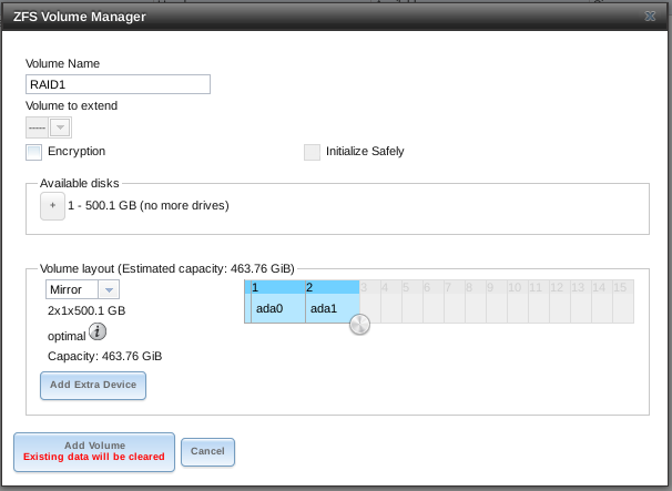
Creating Volumes or Pools which are used to store files on was very easy. Clicking on Storage and then ZFS Volume Manager allowed me to create a new volume with the 2 500 GB hard drives that I had in my NAS, setting them up as RAID1 or Mirror configuration.

Once I’ve gone through the volume manager, I can see my new Pool sitting there waiting for me to dump some data onto it

I had other options too – I could have used only 1 drive for my NAS, or had 2 separate devices within that pool created.
Doing something fatal like detaching the volume painted the screen a bright red, instantly making me aware of the dangers of the action.

Don’t think I’ll be doing that just yet.
Volumes are mounted under the /mnt/ directory, so my just created RAID1 volume can be found under /mnt/RAID1/
It takes just a few clicks to create datasets. Datasets allow you to treat a subdirectory like a filesystem with access controls, compression, and snapshot ability.
Clicking on Storage at the top, then selecting RAID1, and then clicking the New Dataset button down the bottom brings up the new dataset window.
Enter in a name, click add dataset, and it’s created !
Now, time to setup some shares so I can dump data onto the NAS.
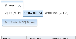
Clicking on the big Sharing button brings up the tabs for Apple (AFP), UNIX (NFS), and Windows (CIFS).
Since I don’t have any Apple or Windows devices, I’ll start setting up a NFS share.
Clicking on the UNIX (NFS) tab gives me a Add Unix (NFS) Share button.
Easy enough.

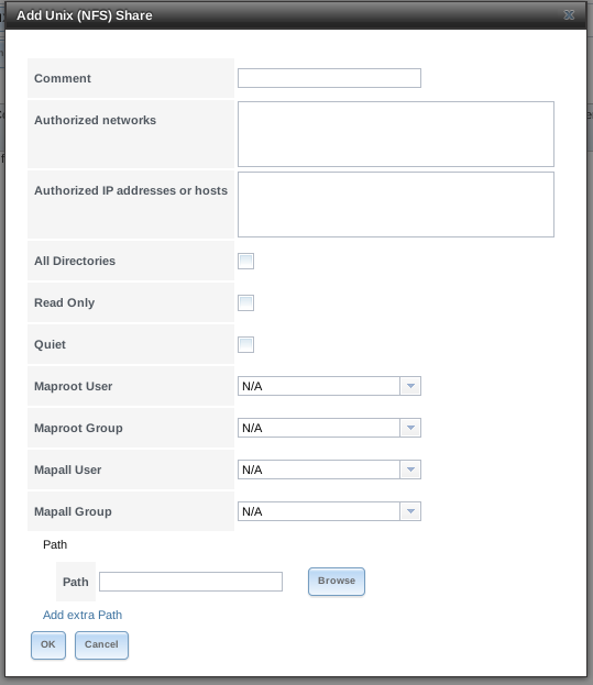
Clicking on that button brings up this window, allowing me to configure the settings for my new NFS share.

Setting up an authorised network, and the path that the share pointed to was easy enough.
After creating the new NFS share, it even asked me if I wanted to enable the NFS service.
After enabling it, I was able to poke it to see if it existed with the showmount command from another computer.
# showmount -e 10.0.0.201

Export list for 10.0.0.201:

/mnt/RAID1 10.0.0.0
As you can see, poking it showed that it was available.
I can now mount the NFS share with a simple command from any linux pc –
mount 10.0.0.201:/mnt/RAID1 /mnt/point
With it mounted, I can now copy and paste files to the NAS !
In my next post, I’ll have a look at FreeNAS’s plugins.
I’ve been wanting to obtain a NAS of some sort for a while now, and after seeing some of the abilities of the Synology NAS enclosures, I was set on just buying one of the Synologies.
However, after looking at the cost of the 4 bay NAS, I wasn’t so sure I could shell out for one.
So I’ve decided to build my own NAS rather than buying a pre-built one.
The pros of building my own is that it’s more flexible than the pre-built ones, and plus I also get some experience with some more Linux Distros on the side !
I’m using some old recycled hardware to save on money as I wanted to shell out as little as possible.
I’ve managed to scrounge up some old old parts to host this NAS on –
Not exactly the latest and greatest, but it should do for the purposes of serving up a few files and whatnot.
The first thing I need to do after I’ve got my hardware, is to choose a Distro.
I’m going to try three distros before I settle on one to actually use as my NAS, just so I can get a feel of the pros and cons of the different distros.
The three that I’ve chosen for this particular project are –
All 3 distros are free to download, so there’s no cost involved in obtaining the distro itself. Support can be bought for FreeNAS and OpenFiler.
A quick rundown on the features, pros, and cons that I’ve found of these 3 Distros so far –
In the next part of this series, I will explore FreeNAS and see what it can do for me.
Originally I was having some issue installing it, so hopefully this time around I can get it to install !
Stay tuned for more 🙂